La présentation de Jonathan Bachrach donne les bases d’utilisation des interfaces Decoupled() en Chisel. Cependant, elle date (2013). Il est donc nécessaire de se mettre un peu à jour.
Tout d’abord, il ne faut pas oublier d’inclure le package :
import chisel3.util._
Ensuite, l’interface possède en elle même l’information de direction. Il ne faut donc pas l’inclure dans un Output()/Input() lorsqu’on le déclare dans un IO(new Bundle {}) :
// Producteur
val data = Decoupled(UInt(10.W))
// Consommateur
val data = Flipped(Decoupled(UInt(10.W)))
Et pour finir, on ne déclare plus de Reg() comme donné à la fin de la présentation. Il faut utiliser RegNext() à la place :
Formal prove is a great method to find bugs into our gateware. But for many years, this was reserved to big companies with lot of $$. Some years ago, Clifford opened the method with it’s synthesis software Yosys. Explanation about formal prove with Yosys-smtbmc and can be found in this presentation. Dan Guisselquist (ZipCPU) give lot of great tutorials on formal prove with Verilog and SystemVerilog design on it’s blog. It’s a good start to learn formal prove.
But, Yosys-smtbmc is made for Verilog (and a bit of SystemVerilog). It’s too bad but it’s the only open source formal tool available for gateware.
How can we prove our VHDL, Clash or Chisel gateware ?
One of the solution consist of writing a TOP component in SystemVerilog that integrate the assume/assert/cover method and instantiate our DUT in it. It’s the way Pepijn De Vos choose for verifying it’s VHDL gateware. Its VHDL code is converted into Verilog with the new GHDL feature not-yet-finished and a systemVerilog top component instantiate the VHDL gateware converted in verilog by GHDL synthesis feature.
That’s an interesting way to do it and it can be done in the same way with Chisel. But it’s a bit limited to input/output ports of our gateware. If we want to add some property about internal counters or flags or others internals states machines registers, we have to export it with some conditional preprocessor value like follows:
`ifdef FORMAL
// Declare some signal output ports
`endif
It’s became little bit difficult to do that with chisel and its blackbox system. Then if we want to include formal property under the verilog generated module, we have to open the generated verilog code and write it directly.
It’s not a lasting solution. Because each time we regenerate Verilog code from Chisel, each time we have to re-write formal properties. It’s rapidly become a pain !
To (temporarily) fix this problem a little python tools has been written by Martoni for injecting rules automatically under generated Verilog module. We will see how it’s work in this article with a simple project named ChisNesPad.
ChisNesPad project
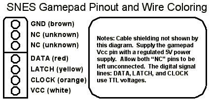
ChisNesPad is a little project that aim to drive Super Nintendo Pad with an FPGA.
In electronic point of view, super nes controller is simply a 16 bits shift register.
The gamepad pinout is relativelly easy to find on the web.
SuperNes gamePAD pinout
For FPGA point of view 3 signals interest us :
DATA : Gamepad output for serial datas
LATCH: Game pad input to take a « picture » of 16 buttons
A command named smtbmcify will then be available on system :
$  smtbmcify -h
Usages:
$ python smtbmcify.py [options]
-h, --help             print this help message
-v, --verilog=module.v verilog module to read
-f, --formal=formal.sv formals rules
-o, --output=name.sv   output filename, default is moduleFormal.sv
To use smtbmc formal tools with smtbmcify we will need two more source/configuration files :
ChisNesPadRules.sv That contain SystemVerilog formals properties
ChisNesPadRules.sby That contain yosys-smtbmc script configuration
These two files must be saved in formal/ directory. sby files are SymbiYosys configuration files, installation instruction of SymbiYosys can be found here.
For simply testing, the rule (written in file ChisNesPadRules.sv) we want to « inject » is following:
//BeginModule:ChisNesPad

always@(posedge clock) begin
    assume(io_dlatch == 1'b1);
    assert(stateReg == 2'b00);
end

//EndModule:ChisNesPad
With this rule, we assert that if io.dlatch output is 1, the internal stateReg will be set to sInit state (00).
The comments BeginModule and EndModule must be set with the exact chisel module name :
//...
class ChisNesPad (val mainClockFreq: Int = 100,
                  val clockFreq: Int = 1,
                  val regLen: Int = 16) extends Module {
  val io = IO(new Bundle{
//...
Hence, the tool smtbmcify will find the module in verilog generated module and inject the rules at the end of it:
Ok the test we done so far PASS without problem. Let’s find a bug adding this rules in ChisNesPadRules.sv :
always@(posedge clock) begin
    assert(regCount <= 16);
end
This rule generate a FAIL :
$ make
cd ..;sbt "runMain chisnespad.ChisNesPad"
[info] Loading project definition from /home/fabien/myapp/chisNesPad/project
[info] Loading settings for project chisnespad from build.sbt ...
[info] Set current project to chisNesPad (in build file:/home/fabien/myapp/chisNesPad/)
[warn] Multiple main classes detected.  Run 'show discoveredMainClasses' to see the list
[info] running chisnespad.ChisNesPad
Generating Verilog sources for ChisNesPad Module
[info] [0.004] Elaborating design...
[info] [1.735] Done elaborating.
Total FIRRTL Compile Time: 1396.1 ms
[success] Total time: 5 s, completed Feb 3, 2020 9:49:48 PM
smtbmcify -v ../ChisNesPad.v -f ChisNesPadRules.sv -o ChisNesPadFormal.sv
Generating file ChisNesPadFormal.sv
1 module will be filled :
ChisNesPad
rm -rf ChisNesPad
sby ChisNesPad.sby
SBY 21:49:48 [ChisNesPad] Copy 'ChisNesPadFormal.sv' to 'ChisNesPad/src/ChisNesPadFormal.sv'.
SBY 21:49:48 [ChisNesPad] engine_0: smtbmc
SBY 21:49:48 [ChisNesPad] base: starting process "cd ChisNesPad/src; yosys -ql ../model/design.log ../model/design.ys"
SBY 21:49:49 [ChisNesPad] base: finished (returncode=0)
SBY 21:49:49 [ChisNesPad] smt2: starting process "cd ChisNesPad/model; yosys -ql design_smt2.log design_smt2.ys"
SBY 21:49:49 [ChisNesPad] smt2: finished (returncode=0)
SBY 21:49:49 [ChisNesPad] engine_0: starting process "cd ChisNesPad; yosys-smtbmc --presat --unroll --noprogress -t 30 --append 0 --dump-vcd engine_0/trace.vcd --dump-vlogtb engine_0/trace_tb.v --dump-smtc engine_0/trace.smtc model/design_smt2.smt2"
SBY 21:49:49 [ChisNesPad] engine_0: ##   0:00:00  Solver: yices
SBY 21:49:49 [ChisNesPad] engine_0: ##   0:00:00  Checking assumptions in step 0..
SBY 21:49:49 [ChisNesPad] engine_0: ##   0:00:00  Checking assertions in step 0..
SBY 21:49:49 [ChisNesPad] engine_0: ##   0:00:00  Checking assumptions in step 1..
SBY 21:49:49 [ChisNesPad] engine_0: ##   0:00:00  Checking assertions in step 1..
SBY 21:49:49 [ChisNesPad] engine_0: ##   0:00:00  BMC failed!
SBY 21:49:49 [ChisNesPad] engine_0: ##   0:00:00  Assert failed in ChisNesPad: ChisNesPadFormal.sv:230
SBY 21:49:49 [ChisNesPad] engine_0: ##   0:00:00  Writing trace to VCD file: engine_0/trace.vcd
SBY 21:49:49 [ChisNesPad] engine_0: ##   0:00:00  Writing trace to Verilog testbench: engine_0/trace_tb.v
SBY 21:49:49 [ChisNesPad] engine_0: ##   0:00:00  Writing trace to constraints file: engine_0/trace.smtc
SBY 21:49:49 [ChisNesPad] engine_0: ##   0:00:00  Status: failed (!)
SBY 21:49:49 [ChisNesPad] engine_0: finished (returncode=1)
SBY 21:49:49 [ChisNesPad] engine_0: Status returned by engine: FAIL
SBY 21:49:49 [ChisNesPad] summary: Elapsed clock time [H:MM:SS (secs)]: 0:00:00 (0)
SBY 21:49:49 [ChisNesPad] summary: Elapsed process time [H:MM:SS (secs)]: 0:00:00 (0)
SBY 21:49:49 [ChisNesPad] summary: engine_0 (smtbmc) returned FAIL
SBY 21:49:49 [ChisNesPad] summary: counterexample trace: ChisNesPad/engine_0/trace.vcd
SBY 21:49:49 [ChisNesPad] DONE (FAIL, rc=2)
make: *** [Makefile:10: ChisNesPad/PASS] Error 2
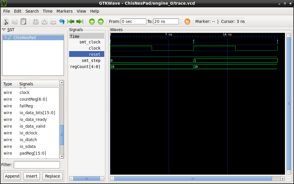
An error is found at second step. A vcd trace is generated that we can see with gtkwave:
$ gtkwave ChisNesPad/engine_0/trace.vcd
Formal engine found a bug, and print it as a VCD trace
We can also get verilog testbench that reproduce the bug under the same directory (trace_tb.v).
The problem here is that we didn’t define initial reset condition as explained in ZipCPU course. To solve this problem we have to change the rule adding initial rules (reset should be set at the begining) and assert counter value only when reset is not set :
initial
    assume(reset==1'b1);

always@(posedge clock) begin
    if(reset == 1'b0)
        assert(regCount <= 16);
end
With that rules, it pass :
$ make
cd ..;sbt "runMain chisnespad.ChisNesPad"
[info] Loading project definition from /home/fabien/myapp/chisNesPad/project
[info] Loading settings for project chisnespad from build.sbt ...
[info] Set current project to chisNesPad (in build file:/home/fabien/myapp/chisNesPad/)
[warn] Multiple main classes detected.  Run 'show discoveredMainClasses' to see the list
[info] running chisnespad.ChisNesPad
Generating Verilog sources for ChisNesPad Module
[info] [0.004] Elaborating design...
[info] [1.612] Done elaborating.
Total FIRRTL Compile Time: 1324.0 ms
[success] Total time: 5 s, completed Feb 3, 2020 10:04:37 PM
smtbmcify -v ../ChisNesPad.v -f ChisNesPadRules.sv -o ChisNesPadFormal.sv
Generating file ChisNesPadFormal.sv
1 module will be filled :
ChisNesPad
rm -rf ChisNesPad
sby ChisNesPad.sby
SBY 22:04:38 [ChisNesPad] Copy 'ChisNesPadFormal.sv' to 'ChisNesPad/src/ChisNesPadFormal.sv'.
SBY 22:04:38 [ChisNesPad] engine_0: smtbmc
SBY 22:04:38 [ChisNesPad] base: starting process "cd ChisNesPad/src; yosys -ql ../model/design.log ../model/design.ys"
SBY 22:04:38 [ChisNesPad] base: finished (returncode=0)
SBY 22:04:38 [ChisNesPad] smt2: starting process "cd ChisNesPad/model; yosys -ql design_smt2.log design_smt2.ys"
SBY 22:04:38 [ChisNesPad] smt2: finished (returncode=0)
SBY 22:04:38 [ChisNesPad] engine_0: starting process "cd ChisNesPad; yosys-smtbmc --presat --unroll --noprogress -t 30 --append 0 --dump-vcd engine_0/trace.vcd --dump-vlogtb engine_0/trace_tb.v --dump-smtc engine_0/trace.smtc model/design_smt2.smt2"
SBY 22:04:38 [ChisNesPad] engine_0: ##   0:00:00  Solver: yices
SBY 22:04:38 [ChisNesPad] engine_0: ##   0:00:00  Checking assumptions in step 0..
[...]
SBY 22:04:39 [ChisNesPad] engine_0: ##   0:00:00  Checking assertions in step 29..
SBY 22:04:39 [ChisNesPad] engine_0: ##   0:00:00  Status: passed
SBY 22:04:39 [ChisNesPad] engine_0: finished (returncode=0)
SBY 22:04:39 [ChisNesPad] engine_0: Status returned by engine: pass
SBY 22:04:39 [ChisNesPad] summary: Elapsed clock time [H:MM:SS (secs)]: 0:00:00 (0)
SBY 22:04:39 [ChisNesPad] summary: Elapsed process time [H:MM:SS (secs)]: 0:00:00 (0)
SBY 22:04:39 [ChisNesPad] summary: engine_0 (smtbmc) returned pass
SBY 22:04:39 [ChisNesPad] DONE (PASS, rc=0)
This is just a little introduction on how to use yosys-smtbmc and symbiYosys to formally prove your chisel design.
Maybe this formal rules injector will be integrated in Chisel a day ?
class RValue (val cSize: Int = 16) extends Bundle {
  val rvalue = Output(UInt(cSize.W))
  val er     = Output(UInt((cSize/2).W))
  val part   = Output(Bool()) /* set if value is partial */
}
And we want to make a register with initialized value we can use the new interface named BundleLiterals:
It can be usefull to be able to test code in console before launching the big compilation. It’s possible in directory where your project build.sbt is :
$ cd myproject/
$ sbt
sbt:myproject> console
scala>
And once in the scala console chisel import can be done :
«Digital Design with Chisel» n’est pas un manuel d’utilisation des ciseaux à bois.
Le livre de Martin Schoerberl «Digital Design with Chisel» est à ma connaissance le premier livre papier concernant le langage de description matériel Chisel.
Le livre — en anglais mais on s’en doute — est une excellente introduction au langage de description matériel Chisel. Avec lui il est même possible de commencer la conception numérique (digital design) en Chisel sans avoir à mettre les mains dans le VHDL ou le Verilog.
Ce manuel se veut un guide pratique de démarrage, on commence avec la description de l’installation des outils pour faire tourner Chisel tout en faisant une (très) rapide introduction à Scala. Scala est le langage utilisé pour Chisel.
Après avoir décrit les composants de bases du langage, l’auteur s’attaque à la description d’un projet Chisel avec l’architecture des sources, testbench et autres makefile et built.sbt . On attaque ensuite les différentes structures un peu plus avancées de la construction numérique comme les machines d’états, les FIFO, ports séries pour aller jusqu’à la conception d’un processeur simple.
Le livre se termine par un chapitre expliquant comment contribuer au projet initié à Berkeley.
C’est un excellent manuel pour mettre le pied à l’étrier de la conception numérique avec un langage moderne (SSHDL). Bien sûr ça n’est pas en 130 pages que l’on fera le tour du langage, ça n’est pas non plus un manuel de référence exhaustif. Pour le manuel de référence on se référera au site officiel, et pour se souvenir des mots clefs on ira télécharger la «cheat sheet».
Le livre est disponible en impression amazon pour ~10$. Comme c’est un livre «libre» il est également disponible avec ses sources sur le github de l’auteur.
Quelque soit le langage HDL utilisé il est très important de se garder la possibilité d’intégrer des modules provenant d’autre langages et/ou n’ayant pas de descriptions HDL.
C’est par exemple le cas des primitives matériel permettant d’instancier des modules intégrés au FPGA du constructeur au moyen de «template» Verilog : sérialiseur/désérialiseur, PLL, entrées/sorties spécifiques, …
BlackBox
Pour intégrer ce genre de module dans son projet Chisel3 on utilise des «BlackBox». L’idée est de décrire les entrées/sorties du module ainsi que ses paramètres, et Chisel se chargera de convertir ça en une déclaration Verilog.
Le problème est assez classique sur les kits de développement de Xilinx qui sont cadencé par une horloge différentielle : Obligé d’instancier un buffer différentiel pour pouvoir récupérer l’horloge. Ce qui n’est pas prévu dans la classe Module de base de Chisel3 puisque l’horloge − tout comme le reset − est implicite.
D’après la documentation Xilinx, le buffer différentiel IBUFDS doit être instancié de la manière suivante en Verilog pour que le logiciel de synthèse le repère et l’instancie correctement:
Cette instanciation est composée de deux paramètres «generic» et de trois entrées sorties.
Une BlackBox() se comporte comme un Module() sans les horloges et reset implicites. De plus le nom des IO est recopié tel quel par Chisel, il n’ajoute pas le préfixe «io_» comme pour un module normale.
Pour déclarer ce buffer différentiel en Chisel il suffira donc d’écrire le code suivant:
import chisel3._
import chisel3.util._
import chisel3.experimental._

class IBUFDS extends BlackBox(
    Map("DIFF_TERM" -> "TRUE",
        "IOSTANDARD" -> "DEFAULT")) {
    val io = IO(new Bundle {
        val O = Output(Clock())
        val I = Input(Clock())
        val IB = Input(Clock())})
}
Le Map en paramètre de la class BlackBox() permet d’ajouter les paramètres «generic» et les entrées sortie sont déclarés par la variable io.
Il suffira alors de l’instancier dans notre module top :
val ibufds = Module(new IBUFDS)
ibufds.io.I := clock_p
ibufds.io.IB:= clock_n
Pour que le code Verilog soit correctement écrit dans le fichier final.
Top RawModule
Maintenant que nous avons notre entrée d’horloge, notre but est d’aller faire clignoter une led (quelle originalité !) en utilisant un compteur. Avec le module suivant:
class Blink extends Module {
    val io = IO(new Bundle {
        val led = Output(Bool())
        })

    val MAX_COUNT = 100000000

    val count = Counter(MAX_COUNT)

    count.inc()

    io.led := 0.U
    when(count.value <= UInt(MAX_COUNT)/2.U){
    io.led := 1.U
    }
}
Ce module étant un module «normal» l’horloge et le reset sont implicite, alors comment allons nous faire pour qu’il soit cadencé par la sortie du buffer IBUFDS ?
On peut simplement les intégrer dans un Module() classique que l’on appellera Top :
class Top extends Module {
  val io = IO(new Bundle {
    val clock_p = Input(Clock())
    val clock_n = Input(Clock())
    val led     = Output(Bool())
  })

  val ibufds = Module(new IBUFDS)
  ibufds.io.I := io.clock_p
  ibufds.io.IB:= io.clock_n

  val blink = Module(new Blink)
  blink.clock := ibufds.io.O
  blink.reset := 1'0
  io.led := blink.io.led }
Notez que pour connecter explicitement l’horloge, la technique est en phase de développement mais il faut désormais utiliser la classe withClockAndReset() pour faire les choses proprement . Plutôt que :
Cette méthode va fonctionner mais elle va nous ajouter les signaux clock et reset implicites. Signaux qui ne serviront pas à grand chose dans notre cas et généreront des warning pénible dans le logiciel de synthèse:
C’est pour cela qu’une nouvelle hiérarchie de classe est en développement pour les Module().
Un module Top est un module un peu spécial en conception HDL. En effet, ce type de module se contente simplement de «relier des boites entre elles». Ce n’est que du tire-fils, pas besoin d’horloge, de registres et autre structures complexes ici.
Dans la nouvelle hiérarchie des classes Module nous avons donc une nouvelle classe appelée RawModule qui apparaît. Ce module n’a plus aucun signaux implicite et se contente de relier les fils. Dans le code Chisel précédent nous pouvons juste renommer Module en RawModule pour voir que les signaux reset et clock disparaissent:
class Top extends RawModule {
Nous obtenons alors une entête Verilog plus propre :
Nous avons tout de même ce préfixe «io_» disgracieux qui peu devenir pénible pour l’intégration, notamment dans certaine plate-forme où le pinout est déjà fourni pour des noms de pin précis.
Il est possible de les éviter avec les RawModule simplement en utilisant plusieurs variable IO() sans Bundle :
class Top extends RawModule {
  val clock_p = IO(Input(Clock()))
  val clock_n = IO(Input(Clock()))
  val led = IO(Output(Bool()))

  val ibufds = Module(new IBUFDS)
  ibufds.io.I := clock_p
  ibufds.io.IB:= clock_n

  withClockAndReset(ibufds.io.O, false.B) {
    val blink = Module(new Blink)
    led := blink.io.led
  }
}
De cette manière c’est le nom exact de la variable qui sera pris en compte pour générer le Verilog:
module Top(
  input   clock_p,
  input   clock_n,
  output  led
);
Et voila comment nous pouvons désormais faire un projet proprement écrit en Chisel de A à Z, ce qui n’était pas le cas avant où nous étions obligé d’encapsuler le projet dans des Top.v écrit à la main, et obligé de les modifier à chaque changement d’interface.
Le code décrit dans cet article se retrouve sur le Blinking Led Projet, dans le répertoire platform. Pour pouvoir le tester correctement, ne pas oublier de télécharger sa propre version de Chisel3 et de merger la branche modhier comme expliqué dans le README.